Guessing insulation wall thickness or adding uncalculated gel packs to passive temperature controlled packaging solutions causes sub-zero freeze damage during the first four hours of closure, premature corner warming before delivery, and rejected pharmaceutical shipments. Engineering a reliable thermal packaging configuration requires balancing six-sided conductive heat ingress (Q_wall) and payload precooling load (Q_precool_payload) against the usable latent heat sink (m_PCM) of conditioned phase-change refrigerants across the full sealed transit window.
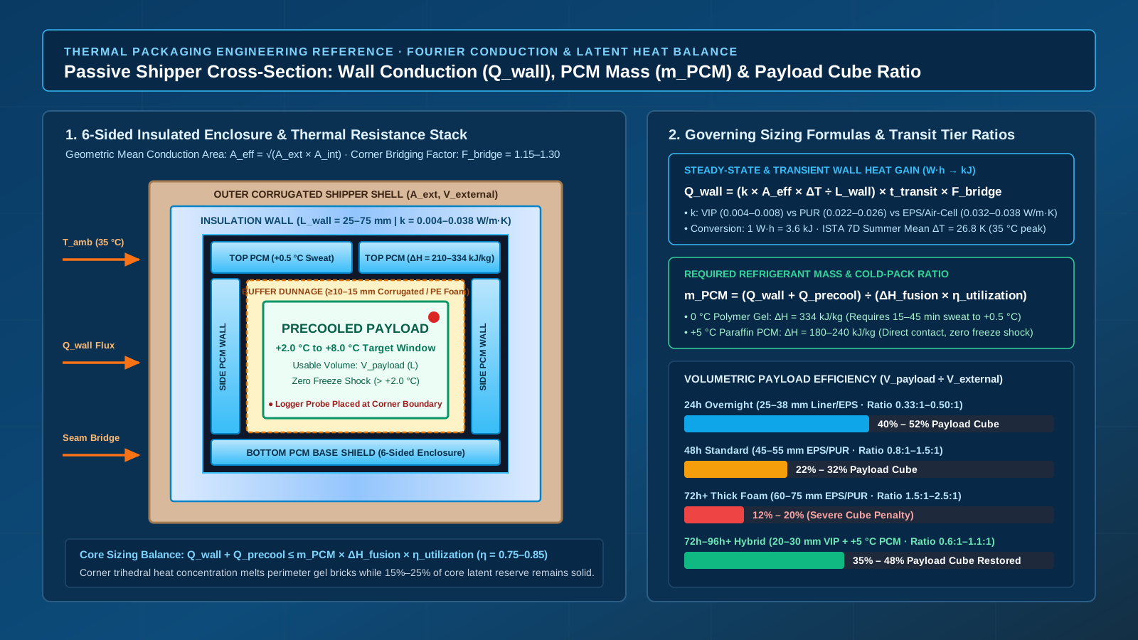
Sizing passive temperature controlled packaging solutions links three quantitative variables: the effective thermal resistance of the six-sided enclosure (L_wall ÷ k evaluated over the geometric mean conduction area A_eff = sqrt(A_ext × A_int) and corner bridging factor F_bridge), the cold pack to payload ratio (m_PCM ÷ m_payload) derived from refrigerant fusion enthalpy (ΔH_fusion × η_utilization), and the volumetric payload efficiency (V_payload ÷ V_external) governing freight cube. Once those thermal boundaries are sized for a 24-hour, 48-hour, or 72-hour profile, packout station controls—bench sweat conditioning to +0.5 °C to +1.0 °C, a 10 to 15 mm conductive buffer barrier, and seasonal top-heavy versus six-sided coolant geometry—keep the payload inside its qualified +2.0 °C to +8.0 °C, +15.0 °C to +25.0 °C, or -20 °C acceptance envelope.
Quick specs: governing parameters for passive payload and PCM sizing
Before selecting an inflatable insulation liner, molded foam container, or vacuum-insulated shipper, lock down the eight governing boundary parameters that couple external route exposure to internal refrigerant mass and usable payload cube.
| Sizing Parameter | Symbol & Units | Engineering Benchmark Range | Primary Reference & Operational Consequence |
|---|---|---|---|
| Enclosure thermal conductivity | k (W/(m·K)) |
0.032–0.038 (Air-Cell / EPS); 0.022–0.026 (PUR); 0.004–0.008 (VIP) |
Cold Chain Technologies White Paper; sets steady-state wall heat flux |
| Effective insulation wall thickness | L_wall (mm or m) |
25–38 mm (24h); 45–55 mm (48h); 60–75 mm (72h foam); 20–30 mm (VIP) |
Measure inflatable and folding liners at corner pinch points (70%–85% nominal) |
| Geometric mean conduction area | A_eff (m²) |
sqrt(A_ext × A_int) across all 6 rectangular faces |
Using A_int alone underpredicts thick-wall heat gain by 25%–45% |
| Corner & seam bridging multiplier | F_bridge (dimensionless) |
1.12–1.18 (molded plug lid); 1.20–1.30 (6-panel VIP or gusseted liner) |
Accounts for 3D trihedral corner conduction and lid-flap seam leakage |
| Phase-change latent enthalpy | ΔH_fusion (kJ/kg) |
334 (0 °C water gel); 180–240 (+5 °C paraffin PCM); 571 (-78.5 °C dry ice) |
Peli BioThermal Crēdo Cube; lower organic PCM enthalpy requires low-k VIP walls |
| Perimeter latent utilization factor | η_utilization (fraction) |
0.75–0.85 (80% standard design screen) |
Corners breach +8.0 °C while 15%–25% of inner coolant slab core remains solid |
| Bench sweat release surface gate | T_surface (°C) |
+0.5 °C to +1.0 °C after 15–45 min at +20 °C to +25 °C room ambient |
WHO TRS 961 Annex 9 Supplement 13; eliminates -20 °C freezer sensible sub-cooling shock |
| Thermal buffer dunnage resistance | L_buffer (mm) / R_buffer |
≥ 10–15 mm corrugated or PE foam (R_buffer = 0.17–0.30 m²·K/W) |
Prevents conductive < +2.0 °C contact freezing against 0.0 °C gel pouches |
This engineering sizing framework connects directly to upstream material selection in inflatable insulation and downstream fault isolation in our cold-chain packout troubleshooting guide. While post-excursion forensics prohibits adding unvalidated coolant to mask an assembly error, upfront thermal calculations establish the exact wall thickness, refrigerant mass, and buffer geometry required before chamber qualification begins.
Takeaway: Size passive shippers by solving the coupled enclosure conduction and refrigerant latent-heat balance over the total sealed duration, never by scaling coolant weight linearly from a shorter lane.
Heat-transfer math for sizing passive temperature controlled packaging solutions
Passive temperature controlled packaging solutions operate as closed thermodynamic buffers with zero powered refrigeration during transit. As documented in the Cold Chain Technologies passive thermal packaging white paper, maintaining a payload inside a strict acceptance band—such as +2.0 °C to +8.0 °C refrigerated, +15.0 °C to +25.0 °C controlled room temperature (CRT), or ≤ -20 °C frozen—requires setting the usable latent energy stored in the phase-change coolant (m_PCM) equal to or greater than the sum of external heat transmission through the container shell (Q_wall) and internal sensible heat released by the payload and dunnage during temperature pull-down (Q_precool_payload).
Step 1: Six-sided Fourier conduction equation with geometric mean area and bridging
Over a sealed transit duration t_transit (which must sum packing-bench staging, carrier linehaul, tarmac transfers, customs holds, and final-mile delivery), conductive heat transfer through a rectangular insulated container follows the modified Fourier conduction equation:
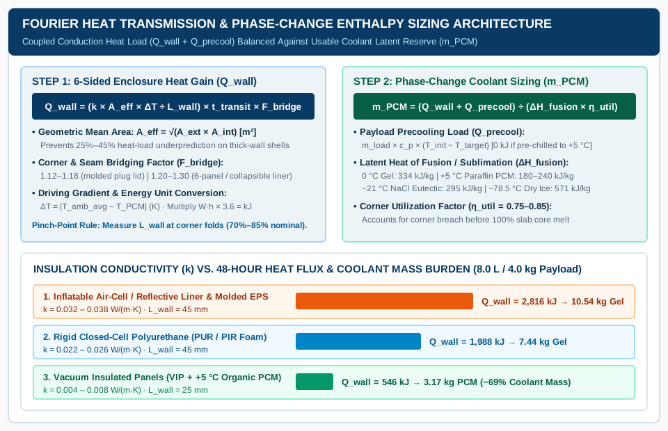
Formula: Q_wall = (k × A_eff × ΔT ÷ L_wall) × t_transit × F_bridge
When k is expressed in W/(m·K), A_eff in m², ΔT in K (or °C), L_wall in m, and t_transit in hours (h), the equation yields cumulative wall heat gain in Watt-hours (W·h). Multiply W·h by 3.6 (1 W = 1 J/s × 3,600 s/h = 3.6 kJ/h) to convert Q_wall into kilojoules (kJ):
Q_wall (kJ) = 3.6 × (k × A_eff × ΔT ÷ L_wall) × t_transit × F_bridge
Each parameter in this conduction model reflects physical container geometry and material structure:
-
Insulation Thermal Conductivity (
k, inW/(m·K)at10 °C to 25 °Cmean wall temperature):- Inflatable Air-Cell / Reflective Bubble Liners & Low-Density Molded EPS (
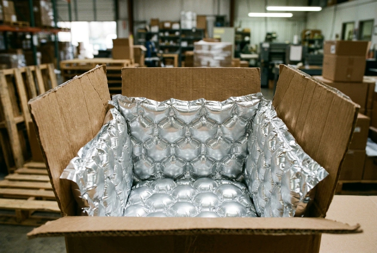
16–20 kg/m³):k = 0.034 to 0.038 W/(m·K). As detailed in Insulated Products Corporation (IPC) box liner specifications and our inflatable insulated packaging assembly guide, air-cellular and self-expanding foam liners trap stagnant dry air layers behind low-emissivity metallized film (emissivity ε ≈ 0.05) to suppress radiant heat transfer across thin25 to 38 mmwalls. - High-Density Molded Expanded Polystyrene (
EPS,24–32 kg/m³) & Extruded Polystyrene (XPS):k = 0.030 to 0.034 W/(m·K). Higher bead fusion density reduces interstitial air permeability and stabilizes corner compression strength. - Rigid Closed-Cell Polyurethane (
PUR) & Polyisocyanurate (PIR) Foam Panels (35–45 kg/m³):k = 0.022 to 0.026 W/(m·K). Cyclopentane- or HFO-blown closed cells reduce gas-phase thermal conductivity by roughly28% to 35%compared with standard EPS. - Vacuum Insulated Panels (
VIP, evacuated fumed-silica core sealed at< 1 to 5 mbarinternal gas pressure): Center-of-panel conductivity reaches0.0040 to 0.0050 W/(m·K). Because multi-layer metallized barrier envelopes conduct heat around panel perimeters, engineers apply an effective installed design value ofk = 0.0060 to 0.0080 W/(m·K)when sizing complete six-panel VIP shippers such as the Peli BioThermal Crēdo Cube.
- Inflatable Air-Cell / Reflective Bubble Liners & Low-Density Molded EPS (
-
Geometric Mean Effective Conduction Area (
A_eff, inm²): A thick-walled rectangular shipping box has an exterior surface areaA_ext = 2 × (L_e × W_e + L_e × H_e + W_e × H_e)that is substantially larger than its interior cavity surface areaA_int = 2 × (L_i × W_i + L_i × H_i + W_i × H_i). Whenever the wall-thickness-to-cavity ratio exceeds0.10(L_wall ÷ L_int > 0.10, which applies to virtually all parcel-sized cold-chain shippers), calculating heat transfer fromA_intalone underpredicts heat gain by25% to 45%, whereas usingA_extalone overestimates corner flux. Three-dimensional conduction shape-factor analysis for thick rectangular shells establishes the geometric mean area:Formula:
A_eff = sqrt(A_ext × A_int) -
Effective Insulation Wall Thickness (
L_wall, inmormm): Measured perpendicular to the six container faces (0.025 mto0.075 m, or25 mmto75 mm). For valve-inflated air-column liners, preformed bubble sleeves, and self-expanding foam pouches,L_wallmust be recorded at the folded corner pinch-point thickness (typically 70% to 85% of the unbent center-of-cushion thickness), because heat flux follows the path of least thermal resistance. -
Time-Weighted Temperature Gradient (
ΔT, inKor°C): Defined as the absolute difference between the time-weighted ambient exposure temperature and the internal coolant phase-change boundary:Formula:
ΔT = |T_ambient_avg − T_phase_change|Under the ISTA Procedure 7D summer temperature cycle (
4 h at 22 °C,2 h at 35 °C,12 h at 30 °C, and6 h at 21 °Cper 24-hour loop), the time-weighted mean external temperature isT_ambient_avg = (4×22 + 2×35 + 12×30 + 6×21) ÷ 24 = 644 ÷ 24 = 26.83 °C(with a35.0 °Cafternoon peak). Against a0.0 °Cwater-gel coolant boundary,ΔT_avg = 26.8 K; against a+5.0 °Corganic paraffin PCM boundary,ΔT_avg = 21.8 K. -
Edge, Corner, and Seam Thermal Bridging Factor (
F_bridge, dimensionless): Even after applyingA_eff, real containers lose thermal efficiency at two-dimensional dihedral edges, three-dimensional trihedral corners, and lid-to-body mating seams:F_bridge = 1.12 to 1.18for one-piece molded EPS or PUR chests with stepped tongue-and-groove plug lids.F_bridge = 1.20 to 1.30for six-panel knock-down VIP shippers with butt-jointed foam encapsulation or collapsible reflective box liners with folded corner gussets and taped top flaps.
Step 2: Phase-change enthalpy and cold pack to payload ratio equation
To hold the internal cavity at equilibrium throughout t_transit, the conditioned refrigerant mass (m_PCM, in kg) must absorb both the cumulative wall heat load (Q_wall) and any sensible heat carried by an imperfectly precooled payload (Q_precool_payload):
Formula: m_PCM = (Q_wall + Q_precool_payload) ÷ (ΔH_fusion × η_utilization)
Where the sensible payload pull-down load (Q_precool_payload, in kJ) is calculated from total payload plus primary/secondary packaging mass (m_payload, in kg), specific heat capacity (c_p_payload, in kJ/(kg·K)), and initial loading temperature offset:
Formula: Q_precool_payload = m_payload × c_p_payload × (T_payload_initial − T_target_equilibrium)
For aqueous biologics, vaccines, and glass vial cartons (c_p_payload ≈ 3.8 to 4.18 kJ/(kg·K)), loading product that has been properly equilibrated at +5.0 °C inside a verified cold room sets Q_precool_payload ≈ 0 kJ. However, if staging delays on a packing dock allow a 5.0 kg biologic payload to warm to +12.0 °C prior to loading (ΔT_pull = 7.0 K above +5.0 °C), the sensible pull-down load reaches Q_precool_payload = 5.0 × 3.8 × 7.0 = 133 kJ. That single staging lapse consumes 0.50 kg of 0 °C gel-pack melting capacity before the outer carton is even taped shut.
| Refrigerant Chemistry & Formulation | Phase-Change Point (T_PCM) |
Latent Heat ΔH_fusion (kJ/kg) |
Bulk Density (kg/L) |
Target Payload Band & Operational Constraint |
|---|---|---|---|---|
Water / cross-linked polymer hydrogel (0 °C gel pack or ice brick) |
0.0 °C (+32.0 °F) |
330 – 334 kJ/kg |
0.98 – 1.00 |
+2 °C to +8 °C; highest latent capacity per USD, but requires 15–45 min bench sweat and ≥ 10–15 mm buffer dunnage to prevent freeze shock |
Organic paraffin / n-tetradecane PCM (+4 °C to +5 °C brick) |
+4.5 °C to +5.5 °C (+40 °F to +42 °F) |
180 – 240 kJ/kg |
0.78 – 0.85 |
+2 °C to +8 °C; phase transition sits inside acceptance band, preventing both summer overheating and winter freezing without buffer dividers |
Organic paraffin / bio-ester CRT PCM (+18 °C to +22 °C panel) |
+20.0 °C to +22.0 °C (+68 °F to +72 °F) |
170 – 210 kJ/kg |
0.80 – 0.86 |
+15 °C to +25 °C CRT; dual-state conditioning required so bricks absorb summer heat and emit latent heat during sub-zero winter transit |
Eutectic sodium chloride brine (-21 °C NaCl-H₂O pack) |
-21.1 °C (-6.0 °F) |
280 – 310 kJ/kg |
1.12 – 1.15 |
-15 °C to -25 °C frozen diagnostics/enzymes; requires -28 °C to -35 °C blast freezer soak (≥ 48 h) to achieve full eutectic solidification |
Solid carbon dioxide (-78.5 °C dry ice pellets/slabs, UN 1845) |
-78.5 °C (-109.3 °F sublimation) |
571 kJ/kg (sublimation at 1 atm) |
1.40 – 1.56 (slab) / 0.80 (pellet) |
≤ -60 °C to -20 °C deep-frozen biologics; vents CO₂ gas (non-airtight carton required) and mandates external mounting of logger electronics |
Why does the denominator include the perimeter latent heat utilization factor (η_utilization = 0.75 to 0.85)? Under WHO Technical Report Series No. 961 Annex 9 Supplement 13, a passive shipper fails qualification the instant any monitored corner of the payload envelope breaches +8.0 °C (or drops below +2.0 °C), not when 100% of the coolant mass has melted. Because external heat flux concentrates at the eight trihedral corners and twelve dihedral edges, perimeter coolant zones liquefy completely and allow local thermal breakthrough while 15% to 25% of the interior slab core remains frozen. Applying η_utilization = 0.80 ensures sufficient latent mass at the vulnerable corners.
Rules-of-Thumb:
- If
L_wall ÷ L_internal > 0.10on any rectangular shipper → calculate conduction using the geometric mean areaA_eff = sqrt(A_ext × A_int)and a bridging factorF_bridge ≥ 1.15, because using internal cavity area alone underestimates required refrigerant mass by25% to 45%. - If switching from
0 °Cwater-gel packs (ΔH_fusion = 334 kJ/kg) to+5 °Corganic paraffin PCM (ΔH_fusion ≈ 210 kJ/kg) without upgrading insulation conductivity (k) → increase total PCM mass by35% to 55%, because organic paraffins store roughly one-third less latent heat per kilogram than water.
Takeaway: Combine A_eff = sqrt(A_ext × A_int), F_bridge = 1.15–1.30, and η_utilization = 0.80 in your sizing spreadsheet so corner heat concentration and incomplete slab melting are accounted for before cutting foam or ordering gel bricks.
Worked example: calculating cold pack to payload ratio for a 48-hour lane
To see how enclosure conductivity (k) and refrigerant chemistry interact to determine the cold pack to payload ratio and outer freight cube, consider a standard 48-hour domestic air-and-ground shipment of refrigerated monoclonal antibody vials (+2.0 °C to +8.0 °C product acceptance limits).
Shipment Boundary Inputs (Conditional Engineering Screening Scenario):
- Payload Mass & Carton Envelope:
m_payload = 4.0 kgof precooled liquid vials packed inside a secondary corrugated carton measuring250 × 200 × 160 mm(V_payload = 8.0 L), equilibrated atT_payload_initial = +5.0 °C(Q_precool_payload = 0 kJ). - Ambient Exposure Profile: ISTA Procedure 7D (07-22) 48-hour Summer step profile (
time-weighted mean T_ambient_avg = 26.8 °C,35.0 °Cdaily peak,t_transit = 48 h). - Candidate Architectures:
- Option A: Conventional
45 mmmolded EPS or heavy self-expanding/inflatable hybrid liner (k = 0.034 W/(m·K)) cooled with0.0 °Cwater-polymer gel bricks (ΔH_fusion = 334 kJ/kg,η_utilization = 0.80) separated from the payload by a15 mmdouble-wall corrugated buffer sleeve. - Option B: High-performance
25 mmVacuum Insulated Panel (VIP) shipper (effective installed k = 0.0065 W/(m·K)) cooled with direct-adjacent+5.0 °Corganic paraffin PCM panels (ΔH_fusion = 210 kJ/kg,η_utilization = 0.82,0 mmbuffer air gap required).
- Option A: Conventional
Option A calculation: 45 mm EPS / inflatable hybrid + 0 °C water-gel packs
-
Internal & External Geometry (
V_internal,V_external,A_eff): Accommodating the250 × 200 × 160 mm(8.0 L) payload carton, a15 mmcorrugated thermal buffer per side (+30 mmper axis), and a30 mmperimeter0 °Cgel-brick cavity (+60 mmper axis) requires internal insulation cavity dimensions of:L_i = 0.340 m,W_i = 0.290 m,H_i = 0.250 mV_internal = 0.340 × 0.290 × 0.250 = 0.02465 m³ = 24.65 LA_int = 2 × (0.340×0.290 + 0.340×0.250 + 0.290×0.250) = 2 × (0.0986 + 0.0850 + 0.0725) = 0.5122 m²
Adding the
L_wall = 0.045 m(45 mmper wall, or+90 mmper axis) insulation shell yields external shipper dimensions of:L_e = 0.430 m,W_e = 0.380 m,H_e = 0.340 mV_external = 0.430 × 0.380 × 0.340 = 0.05556 m³ = 55.56 LA_ext = 2 × (0.430×0.380 + 0.430×0.340 + 0.380×0.340) = 2 × (0.1634 + 0.1462 + 0.1292) = 0.8776 m²A_eff = sqrt(0.8776 × 0.5122) = sqrt(0.4495) = 0.6705 m²
-
48-Hour Conductive Heat Load (
Q_wall): Withk = 0.034 W/(m·K),ΔT = 26.8 − 0.0 = 26.8 K,L_wall = 0.045 m,t_transit = 48 h, andF_bridge = 1.20:Steady Conduction Rate = (0.034 × 0.6705 × 26.8) ÷ 0.045 = 0.61096 ÷ 0.045 = 13.577 WQ_wall (W·h) = 13.577 W × 48 h × 1.20 = 782.0 W·hQ_wall (kJ) = 782.0 W·h × 3.6 kJ/(W·h) = 2,815.3 kJ ≈ 2,816 kJ
-
Required Refrigerant Mass (
m_PCM) & Resulting Ratios:m_PCM = 2,816 kJ ÷ (334 kJ/kg × 0.80) = 2,816 ÷ 267.2 = 10.54 kg(specified as ten1.05 kgor eleven1.00 kgconditioned0 °Cgel bricks).- Cold Pack to Payload Mass Ratio:
10.54 kg coolant ÷ 4.0 kg payload = 2.64 : 1(by mass), or10.54 L coolant ÷ 8.0 L payload = 1.32 : 1(by volume). - Volumetric Payload Efficiency (
V_payload ÷ V_external):8.0 L ÷ 55.56 L = 14.4%. Over85%of the outer shipping cube is consumed by insulation walls, buffer dunnage, and gel bricks.
Option B calculation: 25 mm VIP + +5 °C organic paraffin PCM panels
-
Internal & External Geometry (
V_internal,V_external,A_eff): Because+5.0 °Corganic paraffin PCM panels (phase change at +4.5 °C to +5.5 °C) cannot freeze a+2.0 °C to +8.0 °Cpayload, the15 mmcorrugated freeze-buffer gap is eliminated and the thinner25 mmPCM panels sit directly around the250 × 200 × 160 mmpayload:L_i = 0.300 m,W_i = 0.250 m,H_i = 0.210 m(V_internal = 15.75 L,A_int = 0.3810 m²)- Adding
L_wall = 0.025 m(25 mmVIP + protective EPP/corrugated skin,+50 mmper axis) givesL_e = 0.350 m,W_e = 0.300 m,H_e = 0.260 m(V_external = 27.30 L,A_ext = 0.5480 m²) A_eff = sqrt(0.5480 × 0.3810) = sqrt(0.20879) = 0.4569 m²
-
48-Hour Conductive Heat Load (
Q_wall): Withk = 0.0065 W/(m·K),ΔT = 26.8 − 5.0 = 21.8 K(smaller driving temperature difference because the internal sink sits at+5.0 °Cinstead of0.0 °C),L_wall = 0.025 m,t_transit = 48 h, andF_bridge = 1.22:Steady Conduction Rate = (0.0065 × 0.4569 × 21.8) ÷ 0.025 = 0.06474 ÷ 0.025 = 2.590 WQ_wall (W·h) = 2.590 W × 48 h × 1.22 = 151.67 W·hQ_wall (kJ) = 151.67 W·h × 3.6 kJ/(W·h) = 546.0 kJ
-
Required Refrigerant Mass (
m_PCM) & Resulting Ratios:m_PCM = 546.0 kJ ÷ (210 kJ/kg × 0.82) = 546.0 ÷ 172.2 = 3.17 kg(specified as six0.55 kgencapsulated PCM TIC panels =3.30 kgtotal).- Cold Pack to Payload Mass Ratio:
3.30 kg PCM ÷ 4.0 kg payload = 0.83 : 1—cutting refrigerant weight by68.7%(7.24 kgless coolant per box) despite organic paraffin having lower latent enthalpy per kilogram than water. - Volumetric Payload Efficiency (
V_payload ÷ V_external):8.0 L ÷ 27.30 L = 29.3%—more than doubling payload cube efficiency and cutting external shipping volume from55.56 Lto27.30 L(-50.9%dimensional air-freight volume).
| Parameter / Output Metric | Option A: 45 mm EPS / Inflatable Hybrid + 0 °C Gel |
Option B: 25 mm VIP + +5 °C Organic Paraffin PCM |
Net Engineering Delta (Option B vs. Option A) |
|---|---|---|---|
| Usable payload volume & mass | 8.0 L (250 × 200 × 160 mm), 4.0 kg vials |
8.0 L (250 × 200 × 160 mm), 4.0 kg vials |
Identical product payload duty |
Effective conductivity (k) & wall (L_wall) |
k = 0.034 W/(m·K), L_wall = 45 mm |
k = 0.0065 W/(m·K), L_wall = 25 mm |
80.9% lower thermal conductivity; 44.4% thinner wall |
External dimensions & outer volume (V_external) |
430 × 380 × 340 mm (55.56 L) |
350 × 300 × 260 mm (27.30 L) |
-28.26 L (-50.9% reduction in outer shipping cube) |
Geometric mean area (A_eff) & ΔT_avg |
A_eff = 0.6705 m², ΔT = 26.8 K |
A_eff = 0.4569 m², ΔT = 21.8 K |
-31.9% smaller heat-transfer surface area |
48-hour conductive heat load (Q_wall) |
782.0 W·h (2,816 kJ) |
151.7 W·h (546 kJ) |
-80.6% reduction in cumulative 48h heat ingress |
Required coolant mass (m_PCM) |
10.54 kg (0 °C gel @ 334 kJ/kg) |
3.30 kg (+5 °C PCM @ 210 kJ/kg) |
-7.24 kg (-68.7% reduction in coolant weight) |
| Cold pack to payload mass ratio | 2.64 : 1 (10.54 kg ÷ 4.0 kg) |
0.83 : 1 (3.30 kg ÷ 4.0 kg) |
Drops from heavy ice-dominant pack to sub-1:1 ratio |
| Total gross packed shipment mass | ~15.6 kg (payload + gel + EPS + dunnage) |
~8.8 kg (payload + PCM + VIP shell) |
-6.8 kg (-43.6% lower gross physical weight) |
Volumetric payload efficiency (V_payload ÷ V_ext) |
14.4% (8.0 L ÷ 55.56 L) |
29.3% (8.0 L ÷ 27.30 L) |
+103.5% relative increase in payload cube density |
Notice how these conditional screening results interact with carrier dimensional weight tariffs (L × W × H ÷ 5,000 cm³/kg or ÷ 6,000 cm³/kg depending on express vs. IATA air cargo rules). Under a 5,000 cm³/kg express volumetric divisor, Option A bills at 55,560 ÷ 5,000 = 11.1 kg dimensional weight (15.6 kg actual gross weight), whereas Option B bills at 27,300 ÷ 5,000 = 5.46 kg dimensional weight (8.8 kg actual gross weight). Whenever air-freight lane rates and return logistics justify reusable or hybrid single-use VIP containers, shrinking A_eff and Q_wall simultaneously lowers both physical refrigerant weight and dimensional freight charges. Compare full active versus passive route economics in our active vs. passive cold-chain technologies guide.
Takeaway: Lowering wall thermal conductivity (k) from 0.034 W/(m·K) to 0.0065 W/(m·K) shrinks both L_wall and A_eff, cutting 48-hour heat gain by 80% and reducing the required cold pack to payload ratio from 2.64:1 down to 0.83:1.
Standardized 24h, 48h, and 72h+ thermal packaging configurations and volumetric efficiency
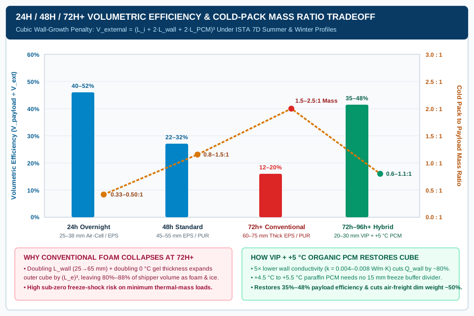
When packaging engineering teams standardize a portfolio of thermal packaging configurations across overnight regional parcel networks (24 h), two-day domestic air/ground lanes (48 h), and three-to-four-day international air-freight routes (72 h to 96 h+), the dominant constraint is the cubic wall-growth penalty:
Formula: V_external = (L_i + 2 × L_wall + 2 × L_PCM + 2 × L_buffer)³
Because exterior container volume grows with the third power of linear wall and coolant thickness additions, attempting to stretch a conventional 0 °C gel + EPS or inflatable liner design from 24 hours to 72+ hours triggers a steep collapse in volumetric payload efficiency (η_vol = V_payload ÷ V_external).
Industry qualification profiles and acceptance boundaries
Standardized configuration tiers are benchmarked against cyclic external temperature exposure profiles defined by ISTA Procedure 7D, Sonoco ThermoSafe lane profile analyses, and WHO TRS 961 Annex 9 Supplement 13:
- ISTA 7D Summer Step Profile (
24 h,48 h,72 h,96 h+loops): Repeats a 24-hour external temperature cycle of4 hours at +22 °C,2 hours at +35 °C,12 hours at +30 °C, and6 hours at +21 °C(time-weighted average +26.8 °C). As analyzed in our ISTA 7D qualification evidence guide, ISTA 7D is a baseline development simulation; routes exposed to tarmac solar radiation or severe desert/tropic heat spikes are evaluated against ISTA 7E or lane-specific telemetry. - ISTA 7D Winter Step Profile: Cycles between
+18 °C (4 h),-10 °C (2 h),-3 °C (12 h)(or severe-20 °Csub-zero winter steps), and+10 °C (6 h), testing whether external sub-zero cold penetrates the insulation and freezes a+2.0 °C to +8.0 °Cor+15.0 °C to +25.0 °Cpayload. - WHO Supplement 13 Dual-Boundary Payload Rule: Every thermal packaging configuration must pass operational qualification (OQ) chamber testing at both minimum payload thermal mass (e.g., a single vial carton representing worst-case vulnerability to sub-zero freeze shock from over-conditioned ice packs and rapid late-transit warming) and maximum payload volume (representing minimum internal dunnage clearance and maximum sensible precooling load).
Master 24h / 48h / 72h+ thermal packaging configuration matrix
The table below synthesizes empirical wall thickness (L_wall), cold pack to payload ratio (m_PCM ÷ m_payload for representative medium-to-maximum payloads), and volumetric payload efficiency (V_payload ÷ V_external) across the four primary passive thermal packaging tiers.
| Transit Tier & Route Duty | Insulation Architecture & k (W/(m·K)) |
Wall Thickness L_wall (mm / in.) |
Refrigerant Chemistry & Buffer Setup | Cold Pack to Payload Mass Ratio | Volumetric Efficiency V_payload ÷ V_ext |
Dominant Qualification Risk & Operational Boundary |
|---|---|---|---|---|---|---|
| 24h Overnight Express (Regional parcel / last-mile, mild-to-moderate summer) | Inflatable air-cell / reflective bubble liner or low-density EPS (k = 0.032–0.038) |
25 – 38 mm (1.0 – 1.5 in.) |
0 °C polymer gel pouches (sweated 15–30 min to +0.5 °C) + 10–15 mm corrugated buffer |
1 : 3 to 1 : 2 (0.33 – 0.50 kg per 1 kg payload) |
40% – 52% |
High cube efficiency and flat-stored liner compactness (IPC CooLiner), but fails if carrier hub delay pushes sealed time past 30–36 h |
| 48h Two-Day Standard (Domestic air/ground network, ISTA 7D Summer/Winter) | High-density molded EPS (0.030–0.034) or rigid polyurethane PUR (0.022–0.026) |
45 – 55 mm (1.75 – 2.2 in.) |
0 °C gel bricks (sweated 20–45 min) + 15 mm PE/corrugated buffer, or dual 0 °C / +5 °C PCM |
0.8 : 1 to 1.5 : 1 (0.80 – 1.50 kg per 1 kg payload; up to 2.5:1 on small loads) |
22% – 32% |
Requires strict seasonal packout switching (Summer top-heavy vs. Winter buffered) to avoid -10 °C winter freeze excursions |
| 72h+ Extended Conventional Foam (3–4 day air + customs hold, foam/gel build) | Thick-wall molded EPS or rigid closed-cell PUR panels (k = 0.023–0.032) |
60 – 75 mm (2.4 – 3.0 in.) |
6-sided 0 °C gel bricks (or -78.5 °C dry ice for frozen) + 15–20 mm buffer divider |
1.5 : 1 to 2.5 : 1 (1.50 – 2.50 kg per 1 kg payload; > 3:1 on min loads) |
12% – 20% |
Severe dimensional freight penalty (80%–88% of outer cube is foam and ice); extreme sub-zero freeze-shock hazard on minimum vial loads |
| 72h–96h+ Hybrid VIP + PCM (International multi-day reusable or single-use VIP) | Vacuum Insulated Panels (VIP, k = 0.004–0.008) + outer EPP or corrugated shell |
20 – 30 mm (0.8 – 1.2 in. VIP core + protective skin) |
Encapsulated +4 °C to +5 °C organic paraffin PCM (2–8 °C) or +20 °C PCM (15–25 °C CRT) |
0.6 : 1 to 1.1 : 1 (0.60 – 1.10 kg PCM per 1 kg payload) |
35% – 48% |
Universal year-round packout protecting against both +35 °C summer and -20 °C winter; requires VIP vacuum-skin rigidity check per Crēdo Series 4 Guide |
Engineering trade-offs across the four configuration tiers
-
Why 24h Inflatable and Reflective Box Liners Maximize Overnight Cube (
40%–52%): On 24-hour regional lanes (t_transit ≤ 24 to 30 h), total cumulative heat ingressQ_wallis small enough that a25 to 38 mmcollapsible air-cell or self-expanding foam liner paired with a0.33:1 to 0.50:1gel-pack-to-payload mass ratio holds+2 °C to +8 °Cacross precooled loads. Because the thin liner wall consumes minimal perimeter depth, usable payload volume remains40% to 52%of the outer corrugated carton, and incoming liners ship uninflated or compressed to reduce warehouse storage space by70% to 85%. However, operators must verify recovered corner thickness and inner-flap clearance at the bench using the checks in our inflatable insulated packaging guide. -
Why 72h+ Conventional Foam Shippers Hit a Geometric Wall (
12%–20%): When transit duration triples from24 hto72 h+, extending hold time solely by thickening EPS or PUR walls (L_wall = 60 to 75 mm) and stacking double layers of0 °Cwater-gel bricks forces outer carton dimensions outward on all six faces. ExpandingA_extincreasesA_eff, which in turn generates additional conductive heat gain that demands still more gel mass. By the time a conventional EPS shipper is qualified for72 to 96 hoursunder ISTA 7D Summer,80% to 88%of the exterior shipping cube consists of insulation foam, dunnage, and water-gel bricks, leaving only12% to 20%for revenue-generating payload. Worse, loading10 to 18 kgof0 °Cgel bricks around a minimum-mass payload (0.2 to 0.5 kgof clinical trial vials) creates an overwhelming cold sink that freezes the payload if bench sweat conditioning varies by even a few minutes. -
How Hybrid VIP + Organic PCM Restores Multi-Day Payload Efficiency (
35%–48%): Replacing a65 mmEPS wall (k = 0.032 W/(m·K)) with a25 mmVacuum Insulated Panel (effective k = 0.0065 W/(m·K)) increases unit thermal resistance (R = L_wall ÷ k) from2.03 (m²·K)/Wto3.85 (m²·K)/W—nearly doubling thermal resistance while cutting wall thickness by40 mmper side (80 mmper axis). Pairing that VIP shell with encapsulated+4.5 °C to +5.5 °Corganic paraffin PCM panels eliminates the15 mmfreeze-buffer dunnage layer and restores volumetric payload efficiency to35% to 48%across72-hour to 96-hour+international lanes.
Rules-of-Thumb:
- If volumetric payload efficiency (
V_payload ÷ V_external) falls below20%or required0 °Cgel mass exceeds2.0 : 1relative to maximum payload mass on a≥ 72 hlane → transition from thick-wall EPS/inflatable liners to a20–30 mmVIP ++5 °CPCM hybrid configuration to cut dimensional air-freight weight by40% to 55%and eliminate minimum-load freeze shock. - If a reusable VIP shipper shows loose, rippled, or soft barrier film on any panel face during pre-packout inspection → quarantine and replace the panel immediately per the Peli BioThermal Crēdo Cube Series 4 User Guide (p. 9), because loss of internal vacuum causes panel conductivity
kto jump fivefold from~0.005 W/(m·K)to~0.026 W/(m·K).
Takeaway: Match insulation architecture to transit duration: use 25–38 mm inflatable or EPS liners for high-cube 24h express lanes, 45–55 mm EPS/PUR for 48h domestic lanes, and 20–30 mm VIP + +5 °C PCM hybrids whenever 72h+ duration would otherwise crush foam payload efficiency below 20%.
Packout geometry and pre-conditioning controls that prevent freeze shock
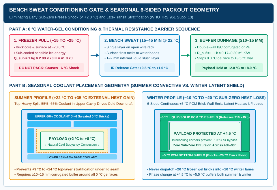
Calculating the right wall thickness (L_wall) and refrigerant mass (m_PCM) solves only half of the thermal engineering problem. Field excursion data analyzed by WHO Supplement 13, Cold Chain Technologies, and Sonoco ThermoSafe shows that a large share of +2.0 °C to +8.0 °C cold-chain failures are self-inflicted sub-zero freeze excursions (< +2.0 °C or < 0.0 °C) during the first 1 to 6 hours after case sealing, or early top-layer warming caused by inverted coolant geometry. Controlling these failure modes requires enforcing three quantitative packout parameters at the packout automation station.
Failure Mode 1: Freezer hard-freeze shock and the bench sweat conditioning gate
Standard 0.0 °C water/polymer hydrogel packs cannot be frozen inside a 0.0 °C chamber because heat transfer requires a finite temperature gradient (ΔT_freeze). Industrial walk-in and blast freezers therefore solidify 0 °C gel bricks at -15.0 °C to -25.0 °C.
When a 1.0 kg frozen gel brick (specific heat of ice c_p_ice = 2.09 kJ/(kg·K)) is pulled directly from a -20.0 °C freezer, it carries a sub-cooled sensible cold reserve below its 0.0 °C melting plateau:
Formula: Q_subcool = m_brick × c_p_ice × (T_phase_change − T_freezer) = 1.0 kg × 2.09 kJ/(kg·K) × (0.0 − (-20.0)) K = 41.8 kJ per kg
In our 48-hour Option A shipper carrying 10.54 kg of gel bricks, loading those bricks hard-frozen at -20.0 °C injects 440.6 kJ of sub-zero sensible cold energy into the sealed cavity. Against a minimum payload of 0.5 kg of vaccine vials (heat capacity ≈ 2.0 kJ/K), that -20.0 °C sensible spike rapidly pulls the internal cavity air and product below -4.0 °C to -8.0 °C during hours 1 to 4—irreversibly denaturing freeze-sensitive protein biologics or alum-adjuvanted vaccines before the gel bricks ever warm up to their 0.0 °C phase-change plateau.
Engineering Control — Two-Step Sweat Conditioning Release Protocol:
- Single-Layer Ambient Staging (
15 to 45 minutes): Transfer frozen0 °Cgel packs from the-20 °Cfreezer onto open wire-mesh racks in a single non-overlapping layer at controlled room ambient (+20 °C to +25 °C) for15 to 45 minutes, following the station sequence in our cold-chain packout process checklist. Never sweat gel bricks while stacked on a pallet, where inner bricks remain at-18 °C. - Quantitative Surface Temperature & Slush Verification Gate (
+0.5 °C to +1.0 °C): Because room temperature and pouch thickness vary, never release coolant on elapsed clock time alone. Before loading, verify that:- Exterior frost has completely melted into liquid condensation droplets (“sweating”);
- Rigid HDPE bricks exhibit a thin (
1 to 2 mm) internal liquid slush layer when gently shaken, confirming the outer ice shell has reached the0.0 °Csolid-liquid phase equilibrium; and - A calibrated infrared (IR) or contact surface thermometer reads
+0.5 °C to +1.0 °C(+32.9 °F to +33.8 °F) across the brick face, proving that100%of the sub-cooled-20 °Csensible reserve (Q_subcool) has been dissipated prior to packout.
Failure Mode 2: Conductive contact freezing and thermal buffer dunnage resistance
Even after a 0.0 °C water-gel pouch passes the +0.5 °C bench sweat check, its phase-change equilibrium (0.0 °C) sits 2.0 °C colder than the +2.0 °C lower survival limit of refrigerated pharmaceuticals. If a 0.0 °C gel pouch presses directly against a primary vial carton, local conductive heat transfer pulls the touching vials down to +0.2 °C to +1.4 °C, triggering a low-temperature excursion on a properly placed packout temperature data logger probe.
Engineering Control — Minimum 10 to 15 mm Thermal Buffer Barrier (R_buffer):
Insert a continuous physical thermal resistance layer (L_buffer ≥ 10 to 15 mm / 0.40 to 0.60 in.) between all 0.0 °C water-gel surfaces and the payload envelope:
Formula: R_buffer = L_buffer ÷ k_buffer
- Double-Wall Corrugated Fiberboard (
B/C Flute,L_buffer = 12 to 15 mm,k_buffer ≈ 0.060 W/(m·K)): ProvidesR_buffer = 0.015 ÷ 0.060 = 0.25 (m²·K)/W, stepping the contact boundary temperature from0.0 °Cat the gel pouch face to+3.0 °C to +4.5 °Cat the product carton wall. - Closed-Cell Polyethylene (
PE) Foam Sheet or Inner Air-Cell Bubble Sleeve (L_buffer = 10 to 12 mm,k_buffer ≈ 0.038 to 0.042 W/(m·K)): ProvidesR_buffer = 0.24 to 0.31 (m²·K)/Wwhile resisting moisture softening from sweating condensation. - Direct-Contact Exception (
+4 °C to +5 °COrganic Paraffin PCM): Encapsulated+4.5 °C to +5.5 °Corganic PCM panels conditioned to their specified release state sit safely above+2.0 °Cthroughout phase transition, allowing direct placement around the payload cavity without a15 mmcorrugated buffer divider.
Failure Mode 3: Seasonal buoyancy stratification vs. winter sub-zero freezing
A single static coolant arrangement cannot handle both +35 °C summer tarmac heat and -15 °C winter ground hubs on conventional 0 °C gel shippers:
| Seasonal Operating Profile | Dominant Heat-Transfer Vector | Required Coolant Mass Split & Geometry | Conditioning State & Thermodynamic Mechanism |
|---|---|---|---|
Summer Profile (External Ambient +22 °C to +35 °C, Heat-Gain Dominant) |
Inward solar/ambient conduction through top lid seam and upper walls; warm air rises while cold dense air sinks | Top-Heavy Convective Split: Allocate 55% to 65% of total m_PCM to the top lid layer and upper perimeter walls; 20%–25% to side walls; 15%–20% to base |
Solid-frozen 0 °C gel packs (sweated to +0.5 °C) or solid +4 °C PCM panels absorb inward heat and drive natural cold buoyancy downdrafts across the payload |
Winter Sub-Zero Profile (External Ambient -10 °C to -20 °C, Heat-Loss Dominant) |
Outward heat loss through all 6 faces—especially the bottom panel resting on sub-zero truck beds and the 8 corners | 6-Sided Continuous Brick-Wall Shield: Surround payload on all 6 faces (top, bottom, and 4 interlocking sides) with zero corner air gaps |
Liquid-conditioned +5 °C organic PCM panels (or partially liquid dual-phase bricks) release latent heat of fusion (180–240 kJ/kg) as they freeze, blocking -20 °C cold from reaching the center |
Controlled Room Temp (CRT, +15 °C to +25 °C) (Year-Round Dual-Risk) |
Both summer overheating (> +25 °C) and winter chilling (< +15 °C) cause excursions |
Symmetric 6-Sided Encapsulated PCM Ring: Equal perimeter coverage across top, bottom, and all 4 vertical walls | +20 °C to +22 °C paraffin/ester PCM conditioned at +17 °C to +19 °C so panels can either melt (absorbing heat at +21 °C) or solidify (releasing heat at +20 °C) |
Rules-of-Thumb:
- If packing
0 °Cwater-based gel bricks pulled from a-20 °Cfreezer into a+2 °C to +8 °Cshipper → enforce a mandatory bench sweat hold (15–45 minon open single-layer wire racks) until surface temperature reaches+0.5 °C to +1.0 °CAND install a≥ 10–15 mmcorrugated or PE foam buffer barrier; skipping either control causes sub-zero freeze shock during hours1 to 4. - If ambient winter route exposure drops below
-5 °C to -10 °Cfor more than6 hours→ never dispatch a summer-configured0 °Cfrozen gel-pack build; switch to a qualified Winter configuration using either liquid-conditioned+5 °Csix-sided PCM panels (which emit latent heat during freezing) or increased insulation wall thickness (L_wall ≥ 50 mm) with reduced coolant mass and15–25 mminternal buffer dunnage.
Takeaway: Prevent early sub-zero excursions and late-transit stratification by pairing an IR-verified +0.5 °C to +1.0 °C bench sweat gate with a ≥ 10–15 mm thermal buffer barrier and seasonal top-heavy (Summer) versus six-sided brick-wall (Winter) coolant placement.
Copyable payload sizing and packout configuration worksheet
Before releasing a new or seasonal thermal packaging configuration to the packing floor, engineering and quality leads should lock down the nine quantitative sizing, mass-ratio, and conditioning parameters in a controlled specification sheet. This record links the mathematical design model directly to ISTA 7D qualification evidence, feeds the shift-level packout station checklist, and scales to unitized bulk containers via the insulated pallet shipper assembly and loading checklist.
| Worksheet Field | Engineering Formula or Verification Method | Sample Specification Entry (48h Summer Biologics) |
|---|---|---|
| 1. Configuration ID & Seasonal Profile | Link packout recipe revision to the exact qualified chamber profile and product temperature band | CFG-48H-SUM-04 (ISTA 7D Summer 48h, +2.0 °C to +8.0 °C refrigerated) |
| 2. Payload Mass & Carton Boundaries | Record both Minimum Payload (freeze-shock & rapid-warming test) and Maximum Payload (volume & precooling test) per WHO Supplement 13 | Min: 0.40 kg (1.2 L) / Max: 4.00 kg (8.0 L @ +5.0 °C verified cold-room precool) |
3. Insulation Material, k & Wall (L_wall) |
Specify core construction, effective conductivity k (W/(m·K)), and minimum corner/pinch wall thickness L_wall (mm) |
Molded EPS (28 kg/m³), k = 0.034 W/(m·K), L_wall = 45 mm (1.77 in.) |
4. Dimensions, Volume & A_eff |
Compute V_external, V_internal, and geometric mean conduction area A_eff = sqrt(A_ext × A_int) (m²) |
Ext: 430×380×340 mm (55.56 L) / Int: 340×290×250 mm (24.65 L) / A_eff = 0.6705 m² |
5. Cumulative Heat Load (Q_total) |
Q_wall = 3.6 × (k × A_eff × ΔT ÷ L_wall) × t_transit × F_bridge (kJ) + Q_precool_payload (kJ) |
Q_wall = 2,816 kJ (F_bridge = 1.20) + Q_precool = 0 kJ → Q_total = 2,816 kJ |
6. Refrigerant SKU & Mass (m_PCM) |
m_PCM = Q_total ÷ (ΔH_fusion × η_utilization); specify exact brick SKU, unit mass, and piece count |
0 °C Polymer Gel Brick (ΔH = 334 kJ/kg, η = 0.80) → 10.54 kg (10 × 1.05 kg bricks) |
| 7. Cold Pack Ratio & Cube Efficiency | Mass Ratio = m_PCM ÷ m_payload_max; Volumetric Efficiency = V_payload ÷ V_external (%) |
Cold Pack to Payload Ratio = 2.64 : 1 / V_payload ÷ V_external = 14.4% |
| 8. Sweat Conditioning Release Gate | Specify freezer soak temperature/duration, open-rack bench sweat window, and calibrated IR surface temperature gate | Freeze ≥ 24h @ -20 °C → Single-layer rack sweat 25–35 min @ +22 °C until IR = +0.5 °C to +1.0 °C |
| 9. Buffer Dunnage & Placement Split | Specify minimum barrier thickness (≥ 10–15 mm), material R_buffer, and top/side/bottom brick count + logger probe position |
15 mm double-wall B/C corrugated sleeve; 4 top, 4 side, 2 bottom bricks; probe at top corner vial box |
Takeaway: Lock all nine sizing and conditioning fields into a version-controlled packout specification before running chamber qualification so operators never improvise brick counts, sweat times, or dunnage thickness at the bench.
Technical basis and scope
This thermal sizing and configuration reference synthesizes passive heat-transfer principles, refrigerant enthalpy benchmarks, and qualification rules from the Cold Chain Technologies passive thermal packaging white paper, WHO Technical Report Series No. 961 Annex 9 Supplement 13 (Qualification of temperature-controlled transport packaging), ISTA Procedure 7D (Edition 07-22), Sonoco ThermoSafe thermal profile guidance, Peli BioThermal Crēdo Cube Series 4 specifications (UG-001-EN-E Rev. F), Insulated Products Corporation (IPC) insulated box liner data, and Sensitech TempTale Ultra Probe documentation. Confirm every calculated wall thickness, phase-change coolant mass ratio, and seasonal conditioning recipe through complete-pack operational qualification at minimum and maximum payload boundaries under the shipment owner’s approved protocol.